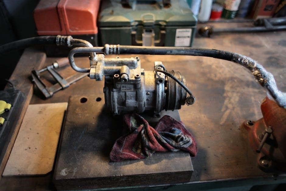
Understanding the 3 phase air compressor pressure switch wiring diagram is crucial for proper installation and repair, using a diagram helps to reduce errors and ensure safety, with detailed wiring information always available online․
Understanding the Components
The 3 phase air compressor pressure switch wiring diagram consists of several key components, including the pressure switch, motor, and power supply․ The pressure switch is a critical component that controls the on/off function of the compressor and monitors the air pressure within the tank․ The motor is responsible for driving the compressor, and the power supply provides the necessary voltage and current to operate the system․ Understanding the function and interaction of these components is essential for proper installation, maintenance, and repair of the compressor․ The diagram provides a detailed illustration of the components and their connections, making it easier to identify and troubleshoot any issues that may arise․ By studying the diagram, users can gain a deeper understanding of the system and its components, allowing them to make informed decisions and take corrective action when necessary․ This knowledge is essential for ensuring the safe and efficient operation of the compressor․

Pressure Switch Functionality
The pressure switch controls the compressor’s on/off function and monitors air pressure, providing automatic shutdown and startup, using a 3 phase air compressor pressure switch wiring diagram for guidance always․
Controlling the Compressor
Controlling the compressor is a critical aspect of the pressure switch’s functionality, as it ensures the compressor operates within a safe and efficient range․ The pressure switch is responsible for turning the compressor on and off, based on the air pressure in the tank․ This is achieved through a series of electrical connections, which are outlined in the 3 phase air compressor pressure switch wiring diagram․ By following this diagram, users can ensure that their compressor is properly controlled, and that it operates in accordance with their specific needs․ The diagram provides a detailed guide to the wiring process, including the connection of the pressure switch to the compressor motor and the power supply․ With this information, users can confidently control their compressor, and enjoy a safe and efficient operating experience․ The compressor control process is fully automated, making it easy to use and maintain․

Importance of a Wiring Diagram
A wiring diagram ensures correct installation and reduces errors, providing a clear guide for 3 phase air compressor pressure switch wiring, with detailed information always available online easily․
Correct Installation and Repairs
A correct installation and repair of a 3 phase air compressor pressure switch is crucial for its proper functioning, and a wiring diagram plays a vital role in this process, providing a clear and detailed guide․
The diagram helps to identify the various components and their connections, making it easier to install and repair the pressure switch․
With a wiring diagram, one can ensure that all the connections are made correctly, reducing the risk of errors and electrical shocks․
The diagram also helps to troubleshoot any issues that may arise during the installation or repair process, making it an essential tool for anyone working with 3 phase air compressor pressure switches․
By following the wiring diagram, one can ensure that the pressure switch is installed and repaired correctly, ensuring the safe and efficient operation of the air compressor․
The importance of a correct installation and repair cannot be overstated, as it helps to prevent accidents and ensures the longevity of the equipment․
A wiring diagram is an indispensable resource for anyone involved in the installation and repair of 3 phase air compressor pressure switches;
It provides a clear and concise guide, making it easier to work with these complex systems․
The diagram helps to simplify the process, reducing the risk of errors and ensuring a successful installation or repair․
Overall, a wiring diagram is a essential tool for correct installation and repairs of 3 phase air compressor pressure switches․

Wiring the Components
Wiring components requires careful connection of pressure switch, motor, and power supply, using a diagram to ensure correct installation and operation, with detailed steps always available online for reference purposes․
Connecting the Pressure Switch and Motor
To connect the pressure switch and motor, it is essential to follow the wiring diagram carefully, ensuring that all connections are secure and correct․ The pressure switch is typically connected to the motor starter, which controls the power supply to the motor․ The motor starter is usually a magnetic starter that consists of a contactor and an overload relay․ The contactor is responsible for connecting and disconnecting the power supply to the motor, while the overload relay protects the motor from overcurrent conditions․ The pressure switch is connected to the contactor, and when the pressure switch closes, it energizes the contactor, which then connects the power supply to the motor․ By following the wiring diagram, you can ensure that the pressure switch and motor are connected correctly, and the air compressor operates safely and efficiently․ The wiring diagram provides a detailed illustration of the connections, making it easier to understand and implement the wiring process․

Troubleshooting Common Issues
Identify and resolve issues using the diagram, checking wiring and connections, ensuring proper installation and repair, with online resources available for guidance and support always․
Identifying and Resolving Problems
To identify and resolve problems with the 3 phase air compressor pressure switch, it is essential to have a thorough understanding of the wiring diagram and the components involved․ The diagram provides a detailed representation of the electrical connections and the relationships between the various parts․ By studying the diagram, technicians can quickly identify potential issues and take corrective action․ Common problems that may arise include faulty wiring, malfunctioning pressure switches, and improper installation․ The diagram can help technicians to troubleshoot these issues and make the necessary repairs․ Additionally, the diagram can be used to verify that the installation is correct and that all safety protocols are in place․ With the help of the diagram, technicians can ensure that the 3 phase air compressor is functioning properly and safely, and that any problems are resolved quickly and efficiently․ This can help to minimize downtime and reduce maintenance costs․
